
Single-zone model of a university building with hydronic heating and CO2-driven ventilation system
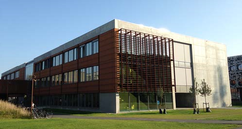
The case study described in more detail in Ref. [1] aims to evaluate energy performance and thermal dynamics of a university teaching building at SDU, Denmark. The building surface area is 8500 m2. There are 3 above-ground floors containing classrooms (40% of floor area), study zones (25%), offices (15%), and common spaces (20%). There is also a basement level containing main HVAC facilities and the main heat exchanger connected to district heating. The building can accommodate maximum 1350 people. The entire building is modelled as a single thermal zone.
The system consists of mainly two parts (Fig.1):
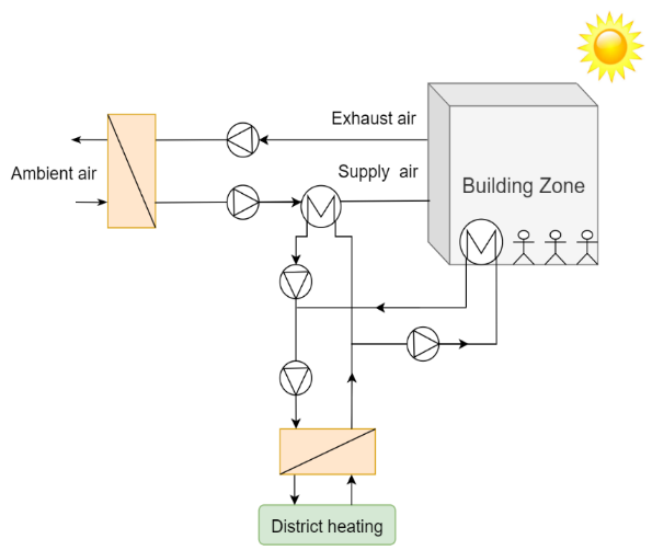
Fig.1 - Schematics of the building energy system
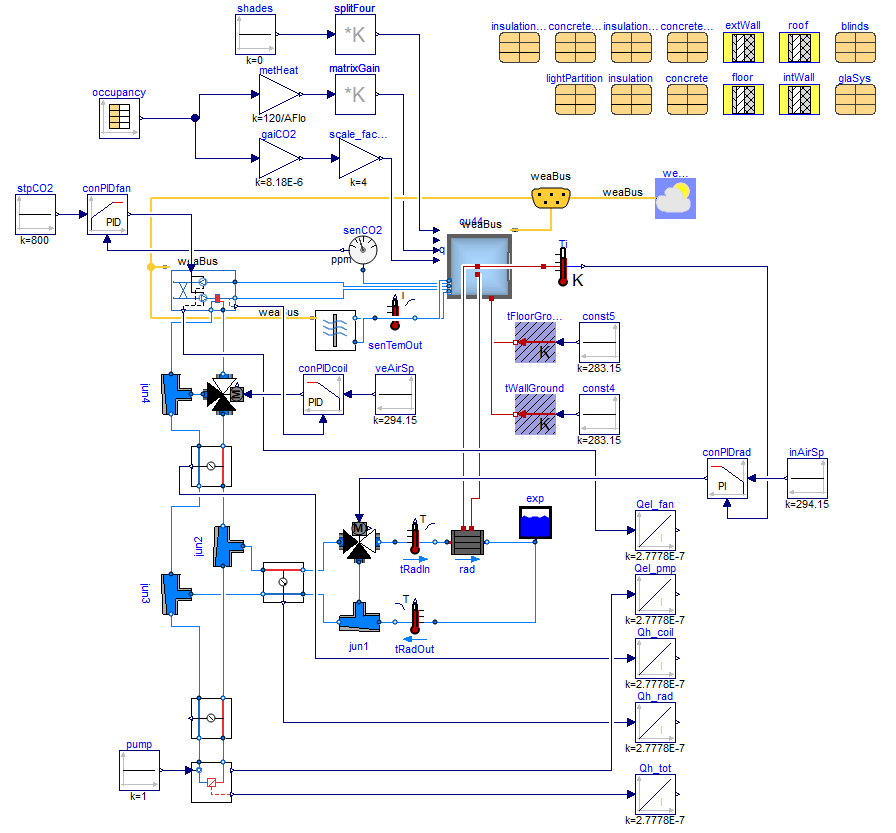
Fig.2 - Modelica model of the energy system
Domestic hot water is supplied by a separate system which is not included in the model. The model has been calibrated based on measured data collected from a large number of sensors. Results from simulation studies show that the model is physically realistic in terms of heat load, electric load and thermal comfort estimation and a new control/actuation setup considerably improves simulation time, achieving relatively small monthly simulation time of 6.4 minutes.
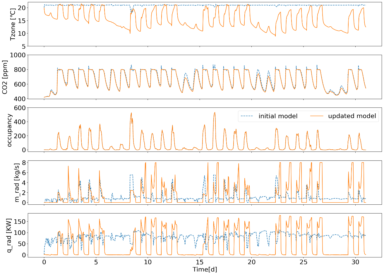
Fig.3 - One-month simulation results
- a hydronic heating loop supplying heat to the building. It has two branches: one goes to indoor radiator, the other proceeds to air handling unit preheating supply air to specific temperature set point. A district heating system is providing heat to ensure supply the hydronic heating circuit.
- a CO2-driven ventilation system that controls indoor CO2 concentration to specified level. Mass flow rate of supply air is controlled ensuring that indoor CO2 concentration does not exceed specific level.
Domestic hot water is supplied by a separate system which is not included in the model. The model has been calibrated based on measured data collected from a large number of sensors. Results from simulation studies show that the model is physically realistic in terms of heat load, electric load and thermal comfort estimation and a new control/actuation setup considerably improves simulation time, achieving relatively small monthly simulation time of 6.4 minutes.
Factsheet
| Number of buildings | 1 |
| Number of thermal zones (per building) | 1 |
| Complexity of thermal zone model | High Order |
| Coupling/Decoupling between district network and buildings | - |
| Simulation tool | Dymola |
| Modelica libraries | Buildings |
| Additional packages/workflows/scripts | - |
| Simulation time | One year with pre-simulation of one month |
| Computational time | 6.4 min for one-month simulation |
| Solver and tolerance | Dassl / 1e-4 |
| CPU speed | 1.9 GHz |
Authors:
Tao Yang (University of Southern Denmark - Denmark)
Konstantin Filonenko (University of Southern Denmark - Denmark)
Christian Veje (University of Southern Denmark - Denmark)
Tao Yang (University of Southern Denmark - Denmark)
Konstantin Filonenko (University of Southern Denmark - Denmark)
Christian Veje (University of Southern Denmark - Denmark)