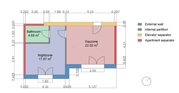
The building is a two room apartment model representing a real case study in Milan, which consists of two rooms and one bathroom. The bathroom and the nightzone are considered together in a single thermal zone. So in total, two thermal zones are considered. The aparment is a newly built heavy construction. The height of each room is 2.7 m, while the other dimensions are reported in the plan below.
The journal paper cited below shows a brief validation of the envelope model using experimental data. However, KPIs results may differ using the latest version of the testcase due to updates with respect to the manuscript version in terms of internal gains, schedules and air mass exchange between the zones.
Zanetti E, Kim D, Blum D, Scoccia R, Aprile M. Performance comparison of quadratic, nonlinear, and mixed integer nonlinear MPC formulations and solvers on an air source heat pump hydronic floor heating system. Journal of Building Performance Simulation. 2022 Sep 15:1-9. [url]
As can be seen from the plan, there are four different types of walls that, with the floor and the ceiling, constitute the boundaries of the thermal zones. All the geometrical and thermal characteristics of the various material layers are highlighted below.
| External wall | |||||||
| N | Description | x [m] |
k [W/(mK)] |
c [J/(kg K)] |
d [kg/m3] |
absIR [-] |
absSol [-] |
|---|---|---|---|---|---|---|---|
| 1 | Exterior plaster | 0.005 | 0.300 | 840 | 1300 | 0.9 | 0.6 |
| 2 | EPS 120 thermal insulation panel | 0.1 | 0.034 | 1250 | 23 | - | - |
| 3 | Masonry brick | 0.3 | 0.207 | 840 | 750 | - | - |
| 4 | Gypsum plaster | 0.02 | 0.570 | 1000 | 1300 | 0.9 | 0.6 |
| Internal partition | |||||||
| N | Description | x [m] |
k [W/(mK)] |
c [J/(kg K)] |
d [kg/m3] |
absIR [-] |
absSol [-] |
|---|---|---|---|---|---|---|---|
| 1 | Gyproc Duragyp panel | 0.0125 | 0.250 | 1000 | 1025 | 0.9 | 0.6 |
| 2 | Plasterboard panel (WALLBOARD 13) | 0.0125 | 0.250 | 1000 | 710 | - | - |
| 3 | Glass wool insulation panel (CTGS Par70) | 0.07 | 0.040 | 840 | 40 | - | - |
| 4 | Plasterboard panel (WALLBOARD 13) | 0.0125 | 0.250 | 1000 | 710 | - | - |
| 5 | Gyproc Duragyp panel | 0.0125 | 0.250 | 1000 | 1025 | 0.9 | 0.6 |
| Elevator separator | |||||||
| N | Description | x [m] |
k [W/(mK)] |
c [J/(kg K)] |
d [kg/m3] |
absIR [-] |
absSol [-] |
|---|---|---|---|---|---|---|---|
| 1 | Gypsum plaster | 0.02 | 0.570 | 1000 | 1300 | 0.9 | 0.6 |
| 2 | Concrete | 0.3 | 2.15 | 880 | 2400 | - | - |
| 3 | Glass wool insulation panel (Par45) | 0.045 | 0.038 | 1030 | 13 | - | - |
| 4 | Plasterboard panel (WALLBOARD 13) | 0.0125 | 0.250 | 1000 | 710 | - | - |
| 5 | Gyproc Duragyp panel | 0.0125 | 0.250 | 1000 | 1025 | 0.9 | 0.6 |
| Apartments separator | |||||||
| N | Description | x [m] |
k [W/(mK)] |
c [J/(kg K)] |
d [kg/m3] |
absIR [-] |
absSol [-] |
|---|---|---|---|---|---|---|---|
| 1 | Gyproc Duragyp panel | 0.0125 | 0.250 | 1000 | 1025 | 0.9 | 0.6 |
| 2 | Plasterboard panel (WALLBOARD 13) | 0.0125 | 0.250 | 1000 | 710 | - | - |
| 3 | Glass wool insulation panel (CTGS Par70) | 0.07 | 0.040 | 840 | 40 | - | - |
| 4 | Plasterboard panel (WALLBOARD 13) | 0.0125 | 0.250 | 1000 | 710 | - | - |
| 5 | Glass wool insulation panel (CTGS Par70) | 0.07 | 0.040 | 840 | 40 | - | - |
| 6 | Plasterboard panel (WALLBOARD 13) | 0.0125 | 0.250 | 1000 | 710 | - | - |
| 7 | Gyproc Duragyp panel | 0.0125 | 0.250 | 1000 | 1025 | 0.9 | 0.6 |
| Ceiling | |||||||
| N | Description | x [m] |
k [W/(mK)] |
c [J/(kg K)] |
d [kg/m3] |
absIR [-] |
absSol [-] |
|---|---|---|---|---|---|---|---|
| 1 | Ceramic tiles | 0.015 | 1.000 | 840 | 2300 | 0.9 | 0.6 |
| 2 | Concrete slab with additive | 0.064 | 1.000 | 880 | 1800 | - | - |
| 3 | Expanded polystyrene | 0.026 | 0.034 | 1300 | 25 | - | - |
| 4 | Isover fonasoft | 0.006 | 0.113 | 2100 | 450 | - | - |
| 5 | Light substrate | 0.105 | 0.100 | 1200 | 400 | - | - |
| 6 | Reinforced concrete (1% steel) | 0.230 | 2.300 | 1000 | 2300 | - | - |
| 7 | Gypsum and sand plaster | 0.200 | 0.800 | 1000 | 1600 | 0.9 | 0.6 |
| Radiant floor | |||||||
| N | Description | x [m] |
k [W/(mK)] |
c [J/(kg K)] |
d [kg/m3] |
absIR [-] |
absSol [-] |
|---|---|---|---|---|---|---|---|
| 1 | Ceramic tiles | 0.015 | 1.000 | 840 | 2300 | 0.9 | 0.6 |
| 2 | Concrete slab with additive | 0.064 | 1.000 | 880 | 1800 | - | - |
| 3 | Expanded polystyrene | 0.026 | 0.034 | 1300 | 25 | - | - |
| 4 | Isover fonasoft | 0.006 | 0.113 | 2100 | 450 | - | - |
| 5 | Light substrate | 0.105 | 0.100 | 1200 | 400 | - | - |
| 6 | Reinforced concrete (1% steel) | 0.230 | 2.300 | 1000 | 2300 | - | - |
| 7 | Gypsum and sand plaster | 0.200 | 0.800 | 1000 | 1600 | 0.9 | 0.6 |
These properties are defined in the model of each thermal zone respectively in the component matExtWal, IntWall,
ElevatorSep, AptSep, roof and slaCon. All the material layers are defined starting from outside to
room-side except for the radiant floor that requires the opposite order, as reported in the Modelica Buildings Library envelope user guide.
Considering the two glazing systems of the small apartment, they have the same construction and shading system, differing only in the dimensions. These characteristics are reported in the tables below.
| Glazing system dimensions | ||
| Room | height [m] |
length [m] |
|---|---|---|
| Day Zone | 2.35 | 2.5 |
| Night Zone | 2.35 | 1.6 |
| Glazing system physical properties | |||||||
| N | Description | x [m] |
k [W/(mK)] |
tauSol [-] |
rhoSol [-] |
tauIR [-] |
absIR [-] |
|---|---|---|---|---|---|---|---|
| 1 | Glass | 0.003 | 1 | 0.6 | 0.075 | 0 | 0.84 |
| 2 | Air | 0.013 | - | - | - | - | |
| 3 | Glass | 0.003 | 1 | 0.075 | 0 | 0.84 | |
| Shading system physical properties | |||
| tauSol [-] |
rhoSol [-] |
tauIR [-] |
absIR [-] |
|---|---|---|---|
| 0.1 | 0.8 | 0 | 0.84 |
The dimensions of the glazing system of the two thermal zones that face towards outside are two parameters that have been defined in the zone components, while the glazing system and shading system physical properties have been defined in the record "Window24".
The thermal zone model also includes the radiant slab component taken from the Modelica Buildings Library. The properties are reported in the following table.
| Radiant slab properties | |
| Pipe distance [m] | 0.1 |
| Interface layer in which pipes are located [-] | 2 |
| Pipe properties | |
| Outer diameter [m] | 0.017 |
| Inner diameter [m] | 0.015 |
| Roughness [m] | 0.000007 |
| Density [kg/m3] | 983 |
| Thermal conductivity [W/(m K)] | 0.4 |
The apartment is occupied from 8 P.M. to 8 A.M. from Monday to Friday by two people, one per thermal zone. The thermal zones are considered unoccupied on Saturday and Sunday.
The heating setpoint is considered 21 [°C] for occupied periods and 16 [°C] for unoccupied periods. The main heat gains come from people, appliances and lighting. For people it corresponds to 60 (W/person) of sensible gains divided equally between convective and radiative contributions and 20 (W) of latent gains. Internal gains for the appliances are 4 (W/m2) and for lighting 1.5 (W/m2) of sensible gains were considred divided equally between convective and radiative contributions. These values are taken from a combination of ASHRAE 90.1 standard and ENI 13200. CO2 generation is 0.0048 L/s per person (Table 5, Persily and De Jonge 2017) and density of CO2 assumed to be 1.8 kg/m^3,making CO2 generation 8.64e-6 kg/s per person.Outside air CO2 concentration is 400 ppm. However, CO2 concentration is not controlled for in the model. Lastly, infilatrations was considered a constant value of 0.5 (vol/h) for each thermal zone.
The climate is assumed to be near Milan, Italy with a latitude and longitude of 45.44,9.27. The climate data comes from the Milano Linate TMY set.
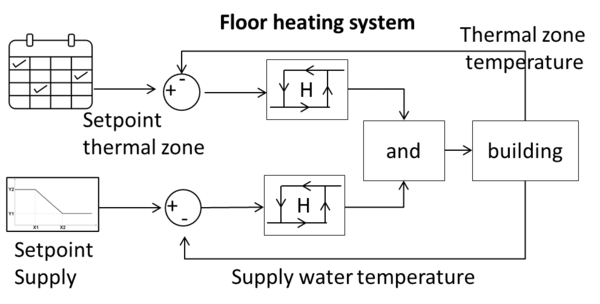
Only heating is considered. The HVAC system is made up of two floor heating circuits, one per thermal zone that can be controlled with a valve. The generation system is an air source heat pump with a nominal heat capacity of 5kW modelled after a Daikin heat pump. Below is reported a schematic view of the HVAC system. Although the baseline controller controls the valves as on-off and the pump with discrete stages, the user can overwrite all control inputs independently with continuous variables, resulting in continuous control.
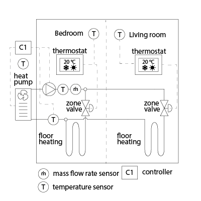
The heating system circulation pump has the default efficiency of the pump model, which is 49%; at the time of writing. The flow rate for each thermal zone floor heating circuit is 620 [l/h]. The heat pump perfomance map is the default map present in the IDEAS Library heat pump model coming from a Daikin heat pump.
hydronicSystem_oveMDayZ_activate [1] [min=0, max=1]: Activation signal to overwrite input hydronicSystem_oveMDayZ_u where 1 activates, 0 deactivates (default value)
hydronicSystem_oveMDayZ_u [1] [min=0.0, max=1.0]: Signal Day zone valve
hydronicSystem_oveMNigZ_activate [1] [min=0, max=1]: Activation signal to overwrite input hydronicSystem_oveMNigZ_u where 1 activates, 0 deactivates (default value)
hydronicSystem_oveMNigZ_u [1] [min=0.0, max=1.0]: Signal Night zone valve
hydronicSystem_oveMpumCon_activate [1] [min=0, max=1]: Activation signal to overwrite input hydronicSystem_oveMpumCon_u where 1 activates, 0 deactivates (default value)
hydronicSystem_oveMpumCon_u [kg/s] [min=0.0, max=5.0]: Mass flow rate control input to circulation pump for water through floor heating system
hydronicSystem_oveTHea_activate [1] [min=0, max=1]: Activation signal to overwrite input hydronicSystem_oveTHea_u where 1 activates, 0 deactivates (default value)
hydronicSystem_oveTHea_u [K] [min=273.15, max=318.15]: Heat system supply temperature
thermostatDayZon_oveTsetZon_activate [1] [min=0, max=1]: Activation signal to overwrite input thermostatDayZon_oveTsetZon_u where 1 activates, 0 deactivates (default value)
thermostatDayZon_oveTsetZon_u [K] [min=273.15, max=318.15]: Setpoint temperature for thermal zone
thermostatNigZon_oveTsetZon_activate [1] [min=0, max=1]: Activation signal to overwrite input thermostatNigZon_oveTsetZon_u where 1 activates, 0 deactivates (default value)
thermostatNigZon_oveTsetZon_u [K] [min=273.15, max=318.15]: Setpoint temperature for thermal zone
dayZon_reaCO2RooAir_y [ppm] [min=None, max=None]: Zone air CO2 concentration
dayZon_reaMFloHea_y [kg/s] [min=None, max=None]: Zone water mass flow rate floor heating
dayZon_reaPLig_y [W] [min=None, max=None]: Lighting power submeter
dayZon_reaPPlu_y [W] [min=None, max=None]: Plug load power submeter
dayZon_reaPowFlooHea_y [W] [min=None, max=None]: Floor heating power
dayZon_reaPowQint_y [W] [min=None, max=None]: Internal heat gains
dayZon_reaTRooAir_y [K] [min=None, max=None]: Zone air temperature
dayZon_reaTavgFloHea_y [K] [min=None, max=None]: Zone average floor temperature
dayZon_reaTretFloHea_y [K] [min=None, max=None]: Zone return water temperature floor heating
dayZon_reaTsupFloHea_y [K] [min=None, max=None]: Zone supply water temperature floor heating
hydronicSystem_reaCOPhp_y [1] [min=None, max=None]: air source heat pump COP
hydronicSystem_reaPPum_y [W] [min=None, max=None]: Pump electrical power
hydronicSystem_reaPeleHeaPum_y [W] [min=None, max=None]: Electric consumption of the heat pump
hydronicSystem_reaTretFloHea_y [K] [min=None, max=None]: Heat pump return water temperature floor heating
nigZon_reaCO2RooAir_y [ppm] [min=None, max=None]: Zone air CO2 concentration
nigZon_reaMFloHea_y [kg/s] [min=None, max=None]: Zone water mass flow rate floor heating
nigZon_reaPLig_y [W] [min=None, max=None]: Lighting power submeter
nigZon_reaPPlu_y [W] [min=None, max=None]: Plug load power submeter
nigZon_reaPowFlooHea_y [W] [min=None, max=None]: Floor heating power
nigZon_reaPowQint_y [W] [min=None, max=None]: Internal heat gains
nigZon_reaTRooAir_y [K] [min=None, max=None]: Zone air temperature
nigZon_reaTavgFloHea_y [K] [min=None, max=None]: Zone average floor temperature
nigZon_reaTretFloHea_y [K] [min=None, max=None]: Zone return water temperature floor heating
nigZon_reaTsupFloHea_y [K] [min=None, max=None]: Zone supply water temperature floor heating
weatherStation_reaWeaCeiHei_y [m] [min=None, max=None]: Cloud cover ceiling height measurement
weatherStation_reaWeaCloTim_y [s] [min=None, max=None]: Day number with units of seconds
weatherStation_reaWeaHDifHor_y [W/m2] [min=None, max=None]: Horizontal diffuse solar radiation measurement
weatherStation_reaWeaHDirNor_y [W/m2] [min=None, max=None]: Direct normal radiation measurement
weatherStation_reaWeaHGloHor_y [W/m2] [min=None, max=None]: Global horizontal solar irradiation measurement
weatherStation_reaWeaHHorIR_y [W/m2] [min=None, max=None]: Horizontal infrared irradiation measurement
weatherStation_reaWeaLat_y [rad] [min=None, max=None]: Latitude of the location
weatherStation_reaWeaLon_y [rad] [min=None, max=None]: Longitude of the location
weatherStation_reaWeaNOpa_y [1] [min=None, max=None]: Opaque sky cover measurement
weatherStation_reaWeaNTot_y [1] [min=None, max=None]: Sky cover measurement
weatherStation_reaWeaPAtm_y [Pa] [min=None, max=None]: Atmospheric pressure measurement
weatherStation_reaWeaRelHum_y [1] [min=None, max=None]: Outside relative humidity measurement
weatherStation_reaWeaSolAlt_y [rad] [min=None, max=None]: Solar altitude angle measurement
weatherStation_reaWeaSolDec_y [rad] [min=None, max=None]: Solar declination angle measurement
weatherStation_reaWeaSolHouAng_y [rad] [min=None, max=None]: Solar hour angle measurement
weatherStation_reaWeaSolTim_y [s] [min=None, max=None]: Solar time
weatherStation_reaWeaSolZen_y [rad] [min=None, max=None]: Solar zenith angle measurement
weatherStation_reaWeaTBlaSky_y [K] [min=None, max=None]: Black-body sky temperature measurement
weatherStation_reaWeaTDewPoi_y [K] [min=None, max=None]: Dew point temperature measurement
weatherStation_reaWeaTDryBul_y [K] [min=None, max=None]: Outside drybulb temperature measurement
weatherStation_reaWeaTWetBul_y [K] [min=None, max=None]: Wet bulb temperature measurement
weatherStation_reaWeaWinDir_y [rad] [min=None, max=None]: Wind direction measurement
weatherStation_reaWeaWinSpe_y [m/s] [min=None, max=None]: Wind speed measurement
EmissionsBiomassPower [kgCO2/kWh]: Kilograms of carbon dioxide to produce 1 kWh thermal from biomass
EmissionsDistrictHeatingPower [kgCO2/kWh]: Kilograms of carbon dioxide to produce 1 kWh thermal district heating
EmissionsElectricPower [kgCO2/kWh]: Kilograms of carbon dioxide to produce 1 kWh of electricity
EmissionsGasPower [kgCO2/kWh]: Kilograms of carbon dioxide to produce 1 kWh thermal from gas
EmissionsSolarThermalPower [kgCO2/kWh]: Kilograms of carbon dioxide to produce 1 kWh thermal from solar irradiation
HDifHor [W/m2]: Horizontal diffuse solar radiation
HDirNor [W/m2]: Direct normal radiation
HGloHor [W/m2]: Horizontal global radiation
InternalGainsCon[Day] [W]: Convective internal gains of zone
InternalGainsCon[Night] [W]: Convective internal gains of zone
InternalGainsLat[Day] [W]: Latent internal gains of zone
InternalGainsLat[Night] [W]: Latent internal gains of zone
InternalGainsRad[Day] [W]: Radiative internal gains of zone
InternalGainsRad[Night] [W]: Radiative internal gains of zone
LowerSetp[Day] [K]: Lower temperature set point for thermal comfort of zone
LowerSetp[Night] [K]: Lower temperature set point for thermal comfort of zone
Occupancy[Day] [number of people]: Number of occupants of zone
Occupancy[Night] [number of people]: Number of occupants of zone
PriceBiomassPower [($/Euro)/kWh]: Price to produce 1 kWh thermal from biomass
PriceDistrictHeatingPower [($/Euro)/kWh]: Price of 1 kWh thermal from district heating
PriceElectricPowerConstant [($/Euro)/kWh]: Completely constant electricity price
PriceElectricPowerDynamic [($/Euro)/kWh]: Electricity price for a day/night tariff
PriceElectricPowerHighlyDynamic [($/Euro)/kWh]: Spot electricity price
PriceGasPower [($/Euro)/kWh]: Price to produce 1 kWh thermal from gas
PriceSolarThermalPower [($/Euro)/kWh]: Price to produce 1 kWh thermal from solar irradiation
TBlaSky [K]: Black Sky temperature
TDewPoi [K]: Dew point temperature
TDryBul [K]: Dry bulb temperature at ground level
TWetBul [K]: Wet bulb temperature
UpperCO2[Day] [ppm]: Upper CO2 set point for indoor air quality of zone
UpperCO2[Night] [ppm]: Upper CO2 set point for indoor air quality of zone
UpperSetp[Day] [K]: Upper temperature set point for thermal comfort of zone
UpperSetp[Night] [K]: Upper temperature set point for thermal comfort of zone
ceiHei [m]: Ceiling height
cloTim [s]: One-based day number in seconds
lat [rad]: Latitude of the location
lon [rad]: Longitude of the location
nOpa [1]: Opaque sky cover [0, 1]
nTot [1]: Total sky Cover [0, 1]
pAtm [Pa]: Atmospheric pressure
relHum [1]: Relative Humidity
solAlt [rad]: Altitude angel
solDec [rad]: Declination angle
solHouAng [rad]: Solar hour angle.
solTim [s]: Solar time
solZen [rad]: Zenith angle
winDir [rad]: Wind direction
winSpe [m/s]: Wind speed
Artificial lighting is provided by LED lights in the thermal zones.
There are no shades on the building.
There is no energy generation or storage on the site.
A moist air model is used, but condensation is not modeled in the HVAC and humidity is not monitored.
The pump is an ideal constant head pump and provided each floor heating circuit with exactly 620 [l/h] if the circuit valve is open.
A constant infiltration flowrate is assumed to be 0.5 ACH.
No further assumptions are needed.
The Peak Heat Day (specifier for /scenario API is 'peak_heat_day') period is:
The Typical Heat Day (specifier for /scenario API is 'typical_heat_day') period is:
The Constant Electricity Price (specifier for /scenario API is 'constant') profile is:
The Dynamic Electricity Price (specifier for /scenario API is 'dynamic') profile is:
The Highly Dynamic Electricity Price (specifier for /scenario API is 'highly_dynamic') profile is:
The Electricity Emissions Factor profile is:
Options for /scenario API are 'low', 'medium', or 'high'.
Empty or None will lead to deterministic forecasts.
See the BOPTEST design documentation for more information.
Options for /scenario API are 'low', 'medium', or 'high'.
Empty or None will lead to deterministic forecasts.
See the BOPTEST design documentation for more information.