
Single-zone emulator (by University of Southern Denmark, modified by SINTEF)
General model description
The overall description of the actual building can be found in the following paper: M. Jradi et al., A World Class Energy Efficient University Building by Danish 2020 Standards, Energy Procedia 132 (2017), 21-26. Some of validation reference data are taken from this paper directly. The following documentation contains only information relevant for the simplified model included in BOPTEST. Additional details regarding the simplified building validattion can be found in the following paper: T. Tang et al.,Implementation and performance analysis of a multi-energy building emulator, In Proc. of 2020 6th IEEE International Energy Conference (ENERGYCon), Sep 28 - Oct 1.
The building surface area is 8500 m2. There are 3 above-ground floors containing classrooms (40% of floor area), study zones (25%), offices (15%), and common spaces (20%). There is also a basement level containing main HVAC facilities and the main heat exchanger connected to district heating. The building can accommodate around 1350 people.
The building thermal envelope is comprised of three different opaque constructions: ground floor (floor), external wall (extWall), and roof (roof). The internal walls are modeled by a single-layer generic construction representing medium-weight partitions. All opaqua construction layers and thermal characteristics are described in Table 1. All windows are modeled using the same contruction type, based on a triple-glass window model from the Buildings library (Buildings.HeatTransfer.Data.GlazingSystems.TripleClearAir13ClearAir13Clear), with the following layers: triple pane, clear glass 3mm, air 12.7 mm, clear glass 3mm, air 12.7 mm, clear glass 3mm.
Table 1: Opaque constructions and their thermal parameters (x - width [m], k - conductivity [W/(mK)], c - specific heat [J/(kgK)], d - density [g/cm3])
|
Construction |
Layers |
Parameters (x, k, c, d) |
|
floor |
Concrete |
0.2, 1.4, 840, 2.24 |
|
|
0.15, 0.04, 1000, 0.05 |
|
|
extWall |
Concrete |
0.2, 1.4, 840, 2.24 |
|
|
0.27, 0.04, 1000, 0.05 |
|
|
roof |
Concrete |
0.27, 1.4, 840, 2.24 |
|
|
0.52, 0.04, 1000, 0.05 |
|
|
intWall |
Generic material |
0.15, 0.5, 1000, 0.25 |
The building is equiped with camera-based sensors that estimate real-time occupants number. Occupancy data is extracted from our internal database"Volta" and stored in "occ.txt" file in the model. Comfort requirements are defined as indoor thermal comfort (temperature) and CO2 concentration, with the temperature setpoint as 21°C during occupied hours (7 AM to 7 PM on weekdays) and 15°C otherwise and CO2 concentration upper limit as 800ppm.
Internal heat gains only consider heat from occupancy. It is assumed that the internal gain per person is 120W and it is evenly distributed over the floor area (i.e. 120 W / 8500 m2). The heat generated per occupant is divided as 40% radiant, 40% convective and 20% latent heat.
The weather data is based on Copenhagen Typical Meteorological Year. The weather file is located in modelica://OU44Emulator/Resources/Weather/DNK_Copenhagen.061800_IWEC.mos.
The actual building is equipped with 4 balanced Air Handling Units (AHU) with heat recovery wheels and pre-heating coils (Fig. 1) and each room is equipped with radiator heating. The heating is provided by district heating grid. Since the model is a single-zone model, all AHUs are modeled with a single AHU oversized by a factor of 4, and all radiators are modeled with a single radiator. The following description covers the HVAC design as implemented in the model, and not the HVAC system in the actual building.
The AHU contains two identical fans, one for supply air and one for extract air.
Figure 1 shows a principle flow sheet for the air handling unit (AHU), as modelled in the emulator. It shows the placement of the sensors and components and the control principle.
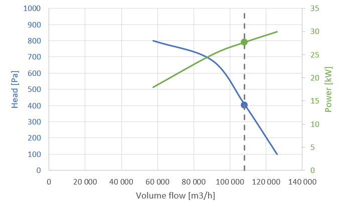
Figure 2 shows the fan characteristics. The grey line shows the operational point at nominal speed. Same fan model is used for both supply and extract fans.
Fig. 1: Principle ventilation flow sheet.
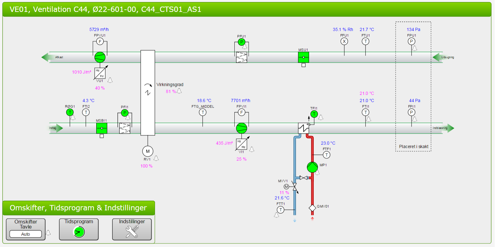
Fig. 2: Fan characteristics.
The layout of the hydronic heating system is shown in Figure 3. Piping segments are modelled between the main distribution pipes and the control valves for both the ventilation and radiator circuits. Piping segments includes heat loss to a fixed external temperature of 20 °C.
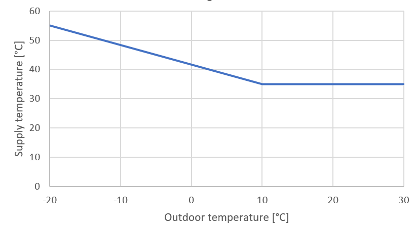
Heat is supplied by a district heating system. The temperature of the district heating is fixed to 65 °C. The supply temperature of the hydronic heating system is controlled by the flow on the primary side of the district heating heat exchanger. The setpoint follows the outdoor temperature compensation curve shown in Figure 4.
The main circulation pump sustains a fixed pressure across the distribution pipes. The baseline setpoint is 50,000 Pa. This is also the maximum possible pressure difference of the pump.
The control valve of the radiator tracks the measured indoor temperature. The baseline controller implements a night setback of 3 K outside of operating hours. After night setback, the setpoint is reset to 22 °C 2 hours before the next operating hour (4 hours on Mondays), to make sure the building has reached the setpoint temperature before the building is occupied again.
Fig. 3: Hydronic heating system as modeled.

Table 1: Design specification of heat exchangers
| System | Nominal Capacity [kW] | Tin_hot [°C] | Tout_hot [°C] | Tin_cold [°C] | Tout_cold [°C] |
|---|---|---|---|---|---|
| District heating | 500 | 65 | 45 | 35 | 55 |
| AHU coil | 250 | 55 | 35 | 14 | 20 |
| Radiator | 255 | 55 | 35 | 21 | 21 |
Fig. 4: Baseline controller outdoor temperature compensation curve.
ahu_oveFanRet_activate [1] [min=0, max=1]: Activation signal to overwrite input ahu_oveFanRet_u where 1 activates, 0 deactivates (default value)
ahu_oveFanRet_u [1] [min=0, max=1]: AHU return fan speed control signal
ahu_oveFanSup_activate [1] [min=0, max=1]: Activation signal to overwrite input ahu_oveFanSup_u where 1 activates, 0 deactivates (default value)
ahu_oveFanSup_u [1] [min=0, max=1]: AHU supply fan speed control signal
dh_oveTSupSetHea_activate [1] [min=0, max=1]: Activation signal to overwrite input dh_oveTSupSetHea_u where 1 activates, 0 deactivates (default value)
dh_oveTSupSetHea_u [K] [min=283.15, max=333.15]: Supply temperature set point for hydronic heating system
oveCO2ZonSet_activate [1] [min=0, max=1]: Activation signal to overwrite input oveCO2ZonSet_u where 1 activates, 0 deactivates (default value)
oveCO2ZonSet_u [ppm] [min=400, max=1000]: Zone CO2 concentration setpoint
ovePum_activate [1] [min=0, max=1]: Activation signal to overwrite input ovePum_u where 1 activates, 0 deactivates (default value)
ovePum_u [Pa] [min=0, max=50000]: Pump dP control signal for heating distribution system
oveTSupSetAir_activate [1] [min=0, max=1]: Activation signal to overwrite input oveTSupSetAir_u where 1 activates, 0 deactivates (default value)
oveTSupSetAir_u [K] [min=288.15, max=313.15]: AHU supply air temperature set point for heating
oveTZonSet_activate [1] [min=0, max=1]: Activation signal to overwrite input oveTZonSet_u where 1 activates, 0 deactivates (default value)
oveTZonSet_u [K] [min=283.15, max=303.15]: Zone temperature set point for heating
oveValCoi_activate [1] [min=0, max=1]: Activation signal to overwrite input oveValCoi_u where 1 activates, 0 deactivates (default value)
oveValCoi_u [1] [min=0, max=1]: AHU heating coil valve control signal
oveValRad_activate [1] [min=0, max=1]: Activation signal to overwrite input oveValRad_u where 1 activates, 0 deactivates (default value)
oveValRad_u [1] [min=0, max=1]: Radiator valve control signal
ahu_reaFloExtAir_y [m3/s] [min=None, max=None]: AHU extract air volume flowrate
ahu_reaFloSupAir_y [m3/s] [min=None, max=None]: AHU supply air volume flowrate
ahu_reaPFanExt_y [W] [min=None, max=None]: Electrical power consumption of AHU extract fan
ahu_reaPFanSup_y [W] [min=None, max=None]: Electrical power consumption of AHU supply fan
ahu_reaTCoiSup_y [K] [min=None, max=None]: AHU heating coil supply water temperature
ahu_reaTHeaRec_y [K] [min=None, max=None]: AHU air temperature exiting heat recovery in supply air stream
ahu_reaTRetAir_y [K] [min=None, max=None]: AHU return air temperature
ahu_reaTSupAir_y [K] [min=None, max=None]: AHU supply air temperature
dh_reaTRetHyd_y [K] [min=None, max=None]: Hydronic heating system return temperature
dh_reaTSupHyd_y [K] [min=None, max=None]: Hydronic heating system supply temperature
reaCO2Zon_y [ppm] [min=None, max=None]: Zone CO2 concentration
reaPPum_y [W] [min=None, max=None]: Electrical power consumption of pump
reaQHea_y [W] [min=None, max=None]: District heating thermal power consumption
reaTCoiRet_y [K] [min=None, max=None]: AHU heating coil return water temperature
reaTZon_y [K] [min=None, max=None]: Zone air temperature
weaSta_reaWeaCeiHei_y [m] [min=None, max=None]: Cloud cover ceiling height measurement
weaSta_reaWeaCloTim_y [s] [min=None, max=None]: Day number with units of seconds
weaSta_reaWeaHDifHor_y [W/m2] [min=None, max=None]: Horizontal diffuse solar radiation measurement
weaSta_reaWeaHDirNor_y [W/m2] [min=None, max=None]: Direct normal radiation measurement
weaSta_reaWeaHGloHor_y [W/m2] [min=None, max=None]: Global horizontal solar irradiation measurement
weaSta_reaWeaHHorIR_y [W/m2] [min=None, max=None]: Horizontal infrared irradiation measurement
weaSta_reaWeaLat_y [rad] [min=None, max=None]: Latitude of the location
weaSta_reaWeaLon_y [rad] [min=None, max=None]: Longitude of the location
weaSta_reaWeaNOpa_y [1] [min=None, max=None]: Opaque sky cover measurement
weaSta_reaWeaNTot_y [1] [min=None, max=None]: Sky cover measurement
weaSta_reaWeaPAtm_y [Pa] [min=None, max=None]: Atmospheric pressure measurement
weaSta_reaWeaRelHum_y [1] [min=None, max=None]: Outside relative humidity measurement
weaSta_reaWeaSolAlt_y [rad] [min=None, max=None]: Solar altitude angle measurement
weaSta_reaWeaSolDec_y [rad] [min=None, max=None]: Solar declination angle measurement
weaSta_reaWeaSolHouAng_y [rad] [min=None, max=None]: Solar hour angle measurement
weaSta_reaWeaSolTim_y [s] [min=None, max=None]: Solar time
weaSta_reaWeaSolZen_y [rad] [min=None, max=None]: Solar zenith angle measurement
weaSta_reaWeaTBlaSky_y [K] [min=None, max=None]: Black-body sky temperature measurement
weaSta_reaWeaTDewPoi_y [K] [min=None, max=None]: Dew point temperature measurement
weaSta_reaWeaTDryBul_y [K] [min=None, max=None]: Outside drybulb temperature measurement
weaSta_reaWeaTWetBul_y [K] [min=None, max=None]: Wet bulb temperature measurement
weaSta_reaWeaWinDir_y [rad] [min=None, max=None]: Wind direction measurement
weaSta_reaWeaWinSpe_y [m/s] [min=None, max=None]: Wind speed measurement
EmissionsBiomassPower [kgCO2/kWh]: Kilograms of carbon dioxide to produce 1 kWh thermal from biomass
EmissionsDistrictHeatingPower [kgCO2/kWh]: Kilograms of carbon dioxide to produce 1 kWh thermal district heating
EmissionsElectricPower [kgCO2/kWh]: Kilograms of carbon dioxide to produce 1 kWh of electricity
EmissionsGasPower [kgCO2/kWh]: Kilograms of carbon dioxide to produce 1 kWh thermal from gas
EmissionsSolarThermalPower [kgCO2/kWh]: Kilograms of carbon dioxide to produce 1 kWh thermal from solar irradiation
HDifHor [W/m2]: Horizontal diffuse solar radiation
HDirNor [W/m2]: Direct normal radiation
HGloHor [W/m2]: Horizontal global radiation
HHorIR [W/m2]: Horizontal infrared irradiation
InternalGainsCon[1] [W]: Convective internal gains of zone
InternalGainsLat[1] [W]: Latent internal gains of zone
InternalGainsRad[1] [W]: Radiative internal gains of zone
LowerSetp[1] [K]: Lower temperature set point for thermal comfort of zone
Occupancy[1] [number of people]: Number of occupants of zone
PriceDistrictHeatingPower [($/Euro)/kWh]: Price of 1 kWh thermal from district heating
PriceElectricPowerConstant [($/Euro)/kWh]: Completely constant electricity price
PriceElectricPowerDynamic [($/Euro)/kWh]: Electricity price for a day/night tariff
PriceElectricPowerHighlyDynamic [($/Euro)/kWh]: Spot electricity price
TBlaSky [K]: Black Sky temperature
TDewPoi [K]: Dew point temperature
TDryBul [K]: Dry bulb temperature at ground level
TWetBul [K]: Wet bulb temperature
UpperCO2[1] [ppm]: Upper CO2 set point for indoor air quality of zone
UpperSetp[1] [K]: Upper temperature set point for thermal comfort of zone
ceiHei [m]: Ceiling height
cloTim [s]: One-based day number in seconds
lat [rad]: Latitude of the location
lon [rad]: Longitude of the location
nOpa [1]: Opaque sky cover [0, 1]
nTot [1]: Total sky Cover [0, 1]
pAtm [Pa]: Atmospheric pressure
relHum [1]: Relative Humidity
solAlt [rad]: Altitude angel
solDec [rad]: Declination angle
solHouAng [rad]: Solar hour angle.
solTim [s]: Solar time
solZen [rad]: Zenith angle
winDir [rad]: Wind direction
winSpe [m/s]: Wind speed
Lighting is not considered in the model.
The model assume there is no shading in the building.
There is no onsite power generation or energy storage in the model.
The model uses moist air despite that no condensation is modelled in any of the used components.
A circulation hot water loop is used to model the heating emission system.
Inflitration is modeled with a fixed ACH parameter (0.2) in addtion to imbalance between supply and extract air flow.
CO2 concentration of the zone is included in the model. We introduce a scale factor of 4 for occupancy CO2 generation to calibrate control of the AHU with real building operation, since the model is lumping unoccupied zones with occupied zones that would drive AHU usage in real building operation.
The major assumptions are as follows:
The Peak Heat Day (specifier for /scenario API is 'peak_heat_day') period
is:
The Typical Heat Day (specifier for /scenario API is 'typical_heat_day')
period is:
Energy Price consists of electric power price and district heating price.
Electric power price:
/scenario API is
'constant') profile is:
obtained from Nordpool DK1: average value for Feb, 2019,
source: https://www.nordpoolgroup.com/Market-data1/Dayahead/Area-Prices/DK/Yearly/?view=table
/scenario API is
'dynamic') profile is: obtained from
from Nordpool DK1: 12 Feb, 2019, using
peak and off peak price of the selected day, source:
https://www.nordpoolgroup.com/Market-data1/Dayahead/Area-Prices/DK/Hourly/?view=table
/scenario API is
'highly_dynamic') profile is: obtained from
Nord pool DK1: day-ahead price, using
hourly price on 12 Feb, 2019,
source:https://www.nordpoolgroup.com/Market-data1/Dayahead/Area-Prices/DK/Hourly/?view=chartDistric heating price=0.0828 euro/kWh,source:https://www.c40.org/case_studies/98-of-copenhagen-city-heating-supplied-by-waste-heat
Two emission factors are considered based on Danish scenario:
Options for /scenario API are 'low', 'medium', or 'high'.
Empty or None will lead to deterministic forecasts.
See the BOPTEST design documentation for more information.
Options for /scenario API are 'low', 'medium', or 'high'.
Empty or None will lead to deterministic forecasts.
See the BOPTEST design documentation for more information.